

 English
  русский
  Français
  Español
  Português
  عربى
عربى 
Submit feedback
Engineering the Modern Road Bike Wheel Hub: Rotational Efficiency, Engagement Dynamics, and Structural Standards
2026-07-09
The Central Role of the Hub in Road Cycling Dynamics
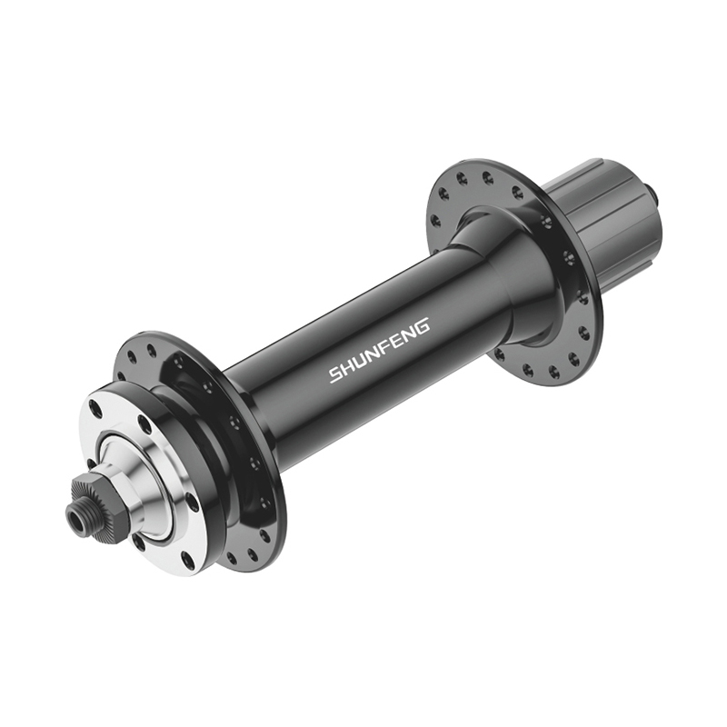
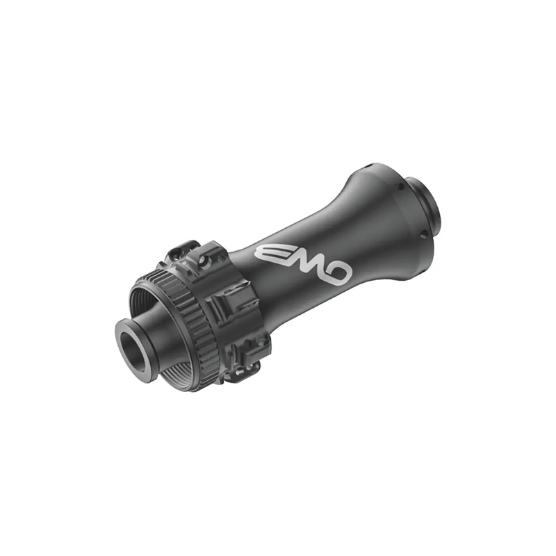
The road bike wheel hub serves as the absolute foundational foundation for wheel structural integrity, rolling resistance management, and drivetrain power transmission. Positioned at the geometric center of the wheel assembly, it must simultaneously support vertical rider weight, absorb violent lateral cornering loads, and convert linear chain tension into immediate forward momentum. Selecting or engineering a high-performance hub requires a meticulous balance between structural mass, bearing frictional coefficients, and mechanical engagement speeds, as any mechanical energy lost at the hub center directly degrades overall cycling velocity and acceleration response.
A primary metric separating high-tier road bicycle hubs from standard utility designs is rotational drag minimization alongside optimized spoke geometry. Minimizing cross-sectional aerodynamic profiles while maximizing the width of the hub flanges drastically changes how a built wheel handles torsion under high-wattage sprints. A highly efficient hub set ensures that upward of 98% of the kinetic energy supplied by the cyclist's legs is directly retained as rotational momentum, rather than dissipating as frictional heat or structural deflection within the wheel chassis.
Structural Anatomy and Material Engineering of Hub Shells
The external shell of a road bike wheel hub must endure exceptional spoke tension, often ranging between 1000 and 1300 Newtons per spoke on the drive side, without experiencing structural distortion or localized cracking at the spoke holes. To achieve this resilience while aggressively managing overall weight, manufacturers rely on highly specialized aluminum metallurgy and precision computer numerical control (CNC) machining workflows.
7075-T6 vs. 6061-T6 Aluminum Alloys
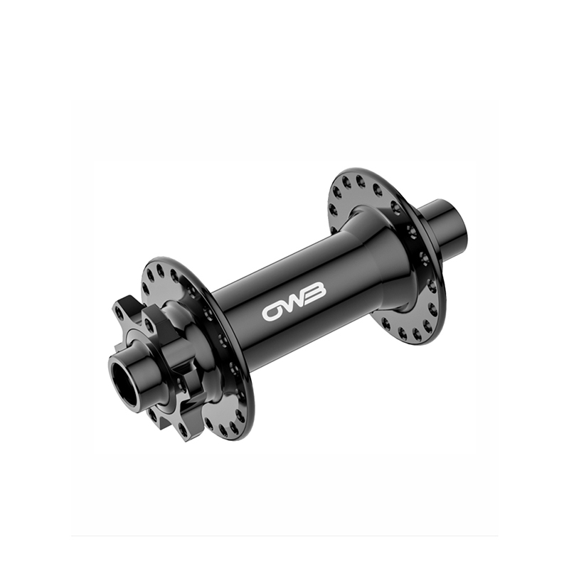
The vast majority of premium road hubs are sculpted from solid forged billets of 7075-T6 or 6061-T6 aluminum. Alloy 7075-T6 utilizes zinc as its primary alloying agent, yielding a tensile strength profile of approximately 570 MPa. This is significantly higher than the 310 MPa limit found in 6061-T6 blends. This elevated strength allows engineers to machine incredibly thin wall profiles and highly minimalist flange structures, yielding a front hub shell that frequently weighs less than 80 grams while safely handling high-tension radial or cross-lacing spoke patterns.
Flange Geometry and the Physics of Wheel Bracing Angles
The physical spacing and diameter of the hub flanges dictate the bracing angles of the spokes, which directly influences the lateral stiffness of the final wheel. Widening the distance from the hub center to the flange improves lateral stability, but moving the drive-side rear flange too far outward can compromise clearance with the rear derailleur cage under maximum cross-chain configurations. Precision hub design positions the non-drive flange as far outboard as possible while calculating a drive-side offset that maintains a balanced tension distribution between both sides of the wheel, reducing the historical 2:1 tension disparity often seen in deep 11-speed and 12-speed drivetrains.
| Material Classification | Ultimate Tensile Strength (MPa) | Yield Strength (MPa) | Density (g/cm³) | Primary Mechanical Advantage |
|---|---|---|---|---|
| 6061-T6 Aluminum | 310 | 276 | 2.70 | Excellent corrosion resistance and ease of forging |
| 7075-T6 Aluminum | 572 | 503 | 2.81 | Ultra-high fatigue limit; tolerates high spoke loads |
| Carbon Fiber Composite | 600 - 1200 | N/A | 1.55 | Maximum weight savings; requires bonded alloy inserts |
Bearing Mechanics: Steel versus Ceramic Interfaces
The ultimate rolling efficiency of any road bike wheel hub is dictated by its internal bearing system. These bearings manage the interface between the stationary axle clamped into the bicycle frame and the rapidly spinning hub shell. Road cycling performance focuses intensely on reducing mechanical friction while maintaining high durability against water, grit, and structural loads.
Modern road hubs utilize either traditional angular contact cup-and-cone bearing systems or sealed industrial cartridge bearings. Cartridge bearings house the inner race, outer race, and rolling elements within a single, pre-assembled ring unit. This makes them exceptionally easy to service or replace when internal wear introduces play into the wheel axle assembly.
High-Precision Steel Bearings
Standard premium hubs rely on high-carbon chromium steel bearings, often graded using the ABEC scale (Annular Bearing Engineers' Committee). Grade 3 and Grade 5 steel bearings provide exceptional durability and roundness tolerances measured in fractions of a micrometer. When packed with high-quality low-viscosity synthetic grease, high-grade steel bearings offer minimal resistance and can survive tens of thousands of kilometers of all-weather riding, provided they are shielded by effective dual-lip contact seals.
Silicon Nitride Ceramic Bearings (Si3N4)
For riders pursuing maximal fractional gains, silicon nitride ceramic balls are installed within specialized steel or treated alloy races. Ceramic balls are roughly 58% lighter than steel counterparts and possess a hardness rating that is up to 120% greater. This exceptional hardness prevents micro-deformation at the point of contact under load, reducing overall rolling resistance. High-end ceramic bearing setups can reduce mechanical friction by approximately 0.2 to 0.8 Watts per hub set at a rolling velocity of 40 kilometers per hour compared to standard steel configurations. However, if the matching steel races are not sufficiently hardened, the ultra-hard ceramic balls can score the tracking surface, accelerating internal pitting and causing structural roughness over time.
Freehub Driver Engagement Technologies
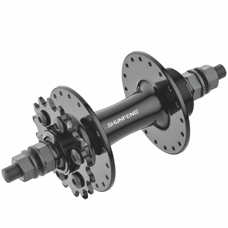
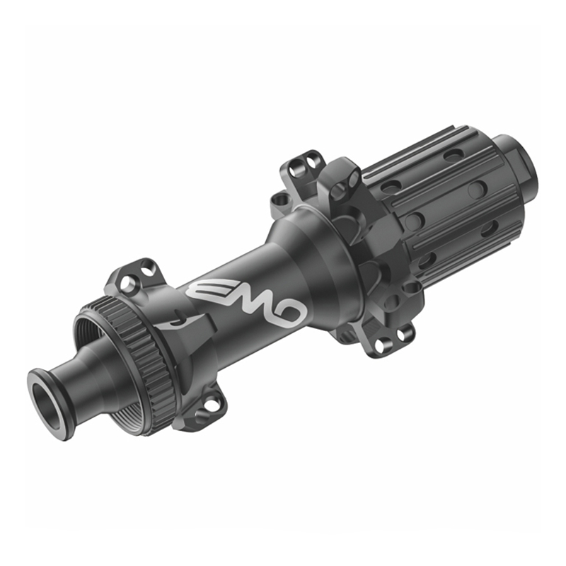
The rear hub houses the freehub driver body, which hosts the multi-gear cassette sprocket cluster and contains the mechanical mechanism that permits coasting while facilitating instant drive engagement when pedaling resumes. The engineering design of this freewheel interface determines the hub's dead-stroke angle, drag profile during coasting, and acoustic output.
Traditional Pawl-and-Ratchet Configurations
The classic engagement mechanism utilizes a series of spring-loaded steel teeth, or pawls, situated on the freehub body that engage an internal geared ring machined inside the hub shell. A standard high-performance configuration might use 4 or 6 pawls aligning with a 36-tooth or 48-tooth drive ring. While highly dependable and simple to overhaul, pawl systems concentrate driving stresses onto small, localized contact points. This layout requires sturdy internal components to prevent structural failure or teeth shearing under high-torque climbing efforts.
Dual Planar Star Ratchet Mechanisms
An alternative mechanism relies on two flat, spring-loaded rings with interlocking teeth that press flat against one another along a parallel plane. When pedaling, all teeth across the entire surface area engage simultaneously, distributing drive forces evenly across a vastly broader structural footprint than pawl-based models. This face-to-face contact format drastically elevates torque handling capabilities and enhances long-term reliability. These systems are available in various tooth counts, typically 18, 36, or 54 teeth, adjusting the mechanical engagement parameters to match specific riding conditions.
| Ratchet Teeth Count | Degrees of Engagement (360° / Teeth) | Coasting Frictional Drag Profile | Primary Application Target |
|---|---|---|---|
| 18 Teeth | 20.0° | Extremely Low Drag | Flat-terrain time trials and long-distance endurance road |
| 36 Teeth | 10.0° | Balanced / Moderate Drag | All-around road racing, rolling hills, and criteriums |
| 54 Teeth | 6.6° | Higher Friction Profile | Technical criteriums, cyclo-cross, and steep alpine climbing |
Increasing the number of engagement points provides a smaller dead-stroke angle, meaning the crank arms need to rotate fewer degrees before the rear hub transfers force to the wheel. While a fast 6.6-degree engagement angle feels highly responsive when accelerating out of tight corners, it does incur a slight penalty in coasting mechanical drag. This occurs because more teeth must slide over one another per second when coasting, requiring a careful engineering assessment of the intended riding discipline.
Axle Standards and Brake Interface Adaptations
The modern road bike wheel hub market has fully consolidated around standardized engineering interfaces designed to handle high mechanical stresses and accommodate advanced braking systems. This transition has largely eliminated traditional quick-release mechanisms on high-performance platforms, replacing them with stiffer and more secure alternatives.
Through-Axle Structural Integration
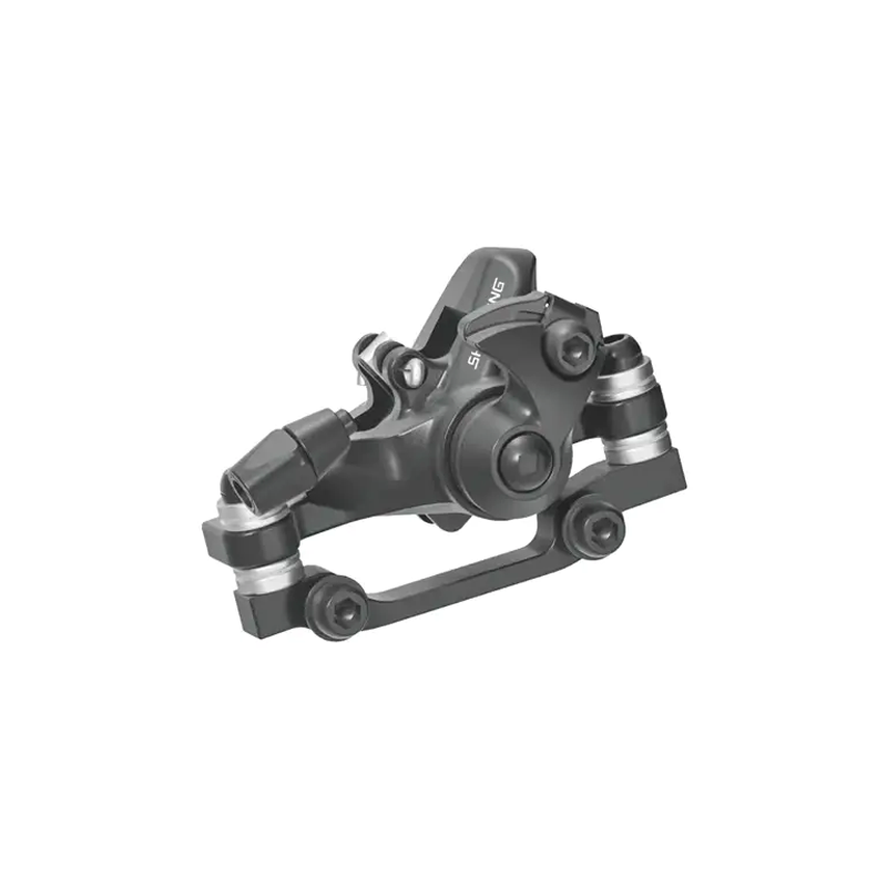
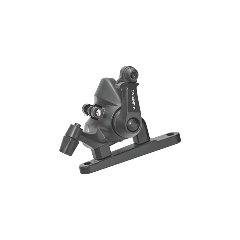
Modern disc-brake road frames rely on hollow through-axles, utilizing a 12mm x 100mm standard for the front hub and a 12mm x 142mm standard for the rear hub. Through-axles pass directly through closed dropouts on the fork and frame, threading securely into place. This closed layout eliminates axle twist under load, providing much higher structural rigidity and ensuring the brake rotor remains perfectly aligned within the caliper pistons during high-load deceleration.
Centerlock vs. Six-Bolt Disc Brake Interfaces
To secure the brake rotors, road bike hubs utilize either a splined Centerlock mounting system or a traditional six-bolt pattern. The Centerlock design uses an engineered splined interface that slips over the hub body and is secured with a single lockring. This design ensures highly precise concentric alignment and distributes braking heat and torque evenly across the splined surface. The six-bolt design, while still common, relies on individual steel fasteners torqued into threaded alloy tabs on the hub flange, requiring precise, balanced tensioning to prevent rotor warping.
Sealing Systems and Tribology in Environmental Protection
The true operational lifespan of a road bike wheel hub is heavily determined by how well its internal components are shielded from environmental contamination. Road spray, fine asphalt dust, and winter road salts can quickly bypass poorly designed sealing systems, causing abrasive wear inside the bearing races and damaging the freehub mechanism.
Hub designers employ two main strategies to manage this environmental exposure:
- Full Contact Labyrinth Seals: These systems feature rubber lips that fit tightly into matching geometric channels machined into the hub body. They provide exceptional defense against pressurized water but introduce a small amount of continuous mechanical drag.
- Non-Contact Matrix Seals: These configurations maintain a microscopic clearance gap between the spinning and stationary surfaces, relying on precise tolerances and grease barriers to deflect water. They eliminate seal drag completely, making them ideal for competitive racing hubs used in controlled, dry conditions.
Tribology, or the science of friction and lubrication, plays a vital role here. Freehub bodies require specialized low-viscosity greases or high-tenacity oils to ensure pawls or ratchets engage instantly in freezing temperatures without sticking. Conversely, internal bearings require a more stable, medium-viscosity grease to maintain a protective film over the rolling elements across high-mileage service intervals.
Technical References
Berto, F. R. (2016). The Dancing Chain: History and Development of the Bicycle Derailleur and Hub Drivetrains. Cycle Publishing.
Wilson, D. G. (2020). Bicycling Science (4th ed.). MIT Press.
German Institute for Standardization. (2022). Cycles - Safety requirements for bicycles - Part 2: Requirements for city and trekking, young adult, mountain and racing bicycles. DIN EN ISO 4210-2.
Bhushan, B. (2013). Introduction to Tribology (2nd ed.). John Wiley & Sons.
 TEL: +86-15356655590
Mobile: +86-18868195070
Email: [email protected]
No. 686, Binhai 2nd Road, Hangzhou Bay New Area, Ningbo City, Zhejiang Province, China
TEL: +86-15356655590
Mobile: +86-18868195070
Email: [email protected]
No. 686, Binhai 2nd Road, Hangzhou Bay New Area, Ningbo City, Zhejiang Province, China
Copyright © Ningbo Shenglu Bicycle Co., Ltd. All Rights
Reserved
Wholesale Bicycle Hub Manufacturers
